
1. Purpose
To create a 3-dimensional (BIM) model of the Engineering Laboratory (Building 17) with terrestrial scans and UAV Photogrammetry. With the collected data, comparisons will be made to further cement our accuracy in comparison to traditional surveying methods. Utilizing these geospatial technologies will help industries improve collaboration, visualization, coordination, efficiency, and maintenance of building projects.
2. Project Planning
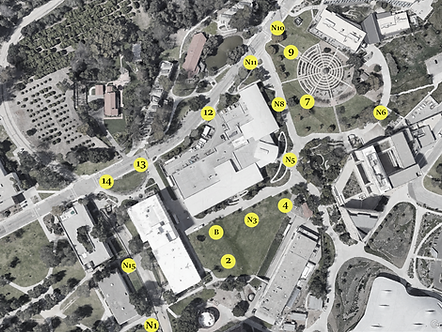
The team reached out to the Facilities Management to obtain the Building Plans of Building 17. Using the Building Plans, it allowed the team to compare existing details and dimensions of site. The UAV planning of the project was created through DroneDeploy, where 15 control points were chosen to get optimal coverage of Building 17. In addition, a pre-flight and post-flight checklist was followed to ensure the set-up and clean-up occurred in an efficient manner. Furthermore, the team requested approval from the CPP Risk Safety Management Department and the Federal Aviation Administration a month before Field Day.
3. Field Day 1: GNSS Survey and UAS Photogrammetry
On September 23rd, 2022, the team conducted a rapid-static survey and an aerial survey for 15 designated points on campus utilizing GNSS equipment, Zenmuse P1 camera, and DJI Matrice 300 RTK Drone. To identify all 15 control points, the team selected Photo Identifiable (Photo ID) points to have a greater precision of data and reduce the margin of error during post-processing.
_JPG.jpg)

4. Field Day 2: Additional Terrestrial Scanning and Data Verification
On November 18, 2022, the team utilized a Trimble TX8 Laser Scanner by using the traverse method with target spheres to gather observations of the atrium and wing walkways for Building 17. On that same day, the team gathered a sample of conventional measurements for different building features with a Trimble S7 Total Station by setting up a reflector on a known point. A tape measurement was used to gather additional measurements and verify the total station measurements.
5. Trimble Post Processing
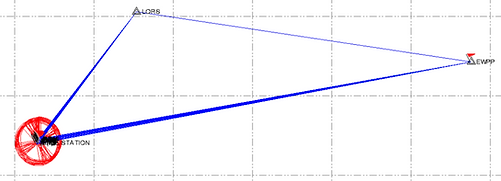
After collecting all the field data, the team began working on the GNSS Data Processing and Photogrammetric Processing to generate a 3-D point cloud. The rapid-static survey was processed through Trimble Business Center (TBC) to perform a constrained network adjustment for all 15 points and the base station with the appropriate project setting (NAD83 and GEOID model 12B - Conus). To ensure that all data was accurate, the team compared the Rapid-Static Adjusted Results with OPUS.

6. Orthophoto Generation
The team processed the flight photos through ContextCapture with georeferenced data from the GPS processing using NAD83 Zone 5 as the horizontal datum and NAVD88 as the vertical datum. All photos were photo-ID'd based on the aerial targets that were clearly visible. Later, quality reports were produced based on the following: NADIR, Oblique 1, and Oblique 2, and Combined. Once reviewed, we proceeded to create our orthophoto, which allowed the team to verify sufficient photo overlap in the collected data before proceeding to processing the point cloud.
7. Point-Cloud Generation
After ensuring the accuracy of the aerial survey, the generation of a point cloud was initiated using Bentley's ContextCapture. The aerial and terrestrial point clouds were merged through cloud-based registration in Trimble RealWorks. The combined point cloud was then compressed to produce a Revit-compatible file, containing 4,854,141 points

8. Revit

Once the point cloud was obtained, the team assembled a 3D model using Revit. The building model was split into four parts: West Wing, East Wing, Atrium, and Roof. Autodesk Construction Cloud was utilized to allow the team to continuously make gradual updates to the model and ensure that no files were lost or duplicated.
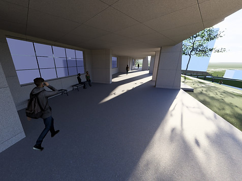
9. Lumion
Once the model was completed, all sections of the building were combined and imported onto Lumion to add/edit the materials or components of the building. With Lumion, the team was able to finalize the materials of the building and add topographic features from the surrounding area.

10. Takeaway

This project demonstrates that BIM models can be a useful tool for the construction industry and allow professional to create and manage digital representations of building projects. With BIM models, engineers are able to to collaborate more effectively by sharing data and information in real-time. Utilizing cloud collaborative websites such as Construction Cloud, and OneDrive, will reduce errors and conflicts during the design/construction process.